An Essential Part of The Wi-Fi Tri-Band System – 5.2 GHz RF Filters
Blog post from our partner: Qorvo
https://www.qorvo.com/design-hub/blog/wifi-5-point-2-ghz-rf-filters
As engineers, we’re always looking for the simplest solution to complex system design challenges. Look no further for solutions in the 5.2 GHz Wi-Fi realm. Here we step you through the resolutions to reduce design complexity, while meeting those tough final product compliance requirements.
An Essential Part of The Wi-Fi Tri-Band System
– 5.2 GHz RF Filters
Most individuals using Wi-Fi in any setting – home, office, or coffee shop – expect a fast upload and download experience. To achieve this, individuals and businesses must move toward a tri-band radio product solution. Anyone familiar with the two Wi-Fi bands of 2.4 GHz and 5 GHz, know the higher 5 GHz band is faster for upload and download speeds. However, the use of higher frequency bands comes at a price of signal attenuation. They also have a high probability of interference with other closely aligned spectrum.
This is where Qorvo filter technology comes in. Qorvo filters help mitigate these probable interferences. In this blog, we focus on the 5.2 GHz filter technology, the higher area of the Wi-Fi tri-band. This filter technology improves the mesh network quality-of-service and helps meet system regulatory requirements.
Wi-Fi and Cellular Frequency Bands
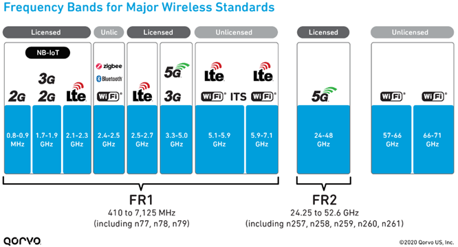
The 5 GHz band provides over six times more bandwidth than 2.4 GHz. This is a big plus for today’s video streaming, chatting, and gaming, which is in high demand. As shown in the figure below, spectrum re-farming and the crowding of wireless standards has increased. As Wi-Fi evolves into even higher realms of 5 GHz and 6 GHz, the crowding continues. As seen in the below figure, the 5 GHz unlicensed area clearly must coexist with cellular frequencies on all sides. One such area is the 5.2 GHz band.

Figure 1: Major wireless frequency bands for 5G Frequency Range (FR) 1 & 2
The Wi-Fi 5.2 GHz Space
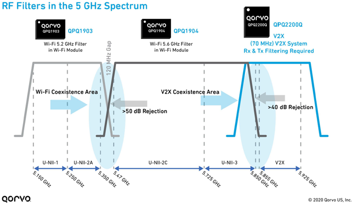
The Wi-Fi 5 GHz UNII (Unlicensed National Information Infrastructure) arena is primarily used in routers in retail, service providers and enterprise spaces. These routers are commonly found in mesh networks, extenders, gateways and outdoor access points. In the UNII1-2a band (i.e. 5150-5350 MHz – 5.2 GHz band), maintaining a minimum RF system pathloss is important. Providing a minimum filter insertion loss is imperative to reduce power consumption, achieve better signal reception, and decrease thermal stress. This helps system designers to deliver low carbon footprint end-products. Additionally, for the 5.2 GHz band, a high out-of-band filter rejection is desired – notably around 50 dB or greater at 5490-5850 MHz – which helps mitigate crosstalk and enables coexistence with the 5.6 GHz UNII band, as shown in Figure 2 below.
5.2 GHz Filter Deep-Dive Analysis (QPQ1903)
To meet the need of the true mesh tri-band application, a well-designed filter is required. Today, few filter suppliers can meet the standard’s body specifications of rejection, insertion loss and power handling in the 5.2 GHz band. As shown in the below figure, Qorvo provides several filter solutions for the UNII 5 GHz bands.

Figure 2: 5 GHz UNII frequency bands, bandwidths, bandedge parameters, and filters
A Review of The Wi-Fi Standard Specifications
High Rejection – A high rejection is critical in a system for two main reasons – one being the need to mitigate interference, and two, to mitigate unwanted signal noise. Therefore, customers and standards bodies have set a desired high parameter of 50 dB or greater on rejection rate for critical out-of-band signals. But it is important to achieve this without losing the integrity of the RF signal range and capacity. Using Qorvo bandBoost™ filters such as the QPQ1903 achieves this goal.
Learn More about Qorvo’s bandBoost™ filters:
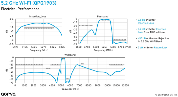
As noted in Figure 2 above, coexistence with the Wi-Fi 5.6 GHz band has only a 120 MHz gap. Meeting the 50 dB or greater rejection at this frequency (5490-5850 MHz) within this small gap is challenging. It requires filter technologies with steep out-of-band skirts and a high rejection rate. BAW (bulk acoustic wave) SMR (solidly mounted resonator) technology is well suited to meet thermal and high rejection filter requirements. BAW-SMR has a vertical heat flux acoustic reflector that allows thermal heat to dissipate away quickly and efficiently from the filter. BAW exhibits very little frequency shifts due to self-heating as the topology of BAW-SMR provides a lower resistance, preventing the resonators from overheating. As shown in Figure 3 below, the rejection rate of the 120 MHz gap is greater than 50 dB, well within the regulatory guidance parameters.

Figure 3: 5.2 GHz QPQ1903 performance measurements @ 25⁰C
Insertion Loss – In Figure 3 above, the insertion loss performance data for the 5.2 GHz bandBoost™ filter, QPQ1903, is 1.5 dB or better. Thus, providing improved system pathloss and power consumption. This translates directly to increased coverage range, better reception of the signal and simplified thermal management of the end product. Additionally, the return loss (not shown) meets the required specification by 2 dB or better across the entire pass band. This allows for an easier system match when using a discrete 5.2 GHz filter solution, which is especially critical in high linearity Wi-Fi 6 systems.
Power Handling – Power handling has become a major requirement for today’s wireless systems. 5G and the increases in RF input power levels to the receiver have attributed heavily to this new high-power handling system requirement. Thus, RF filters must be able to meet higher input power levels, sometimes up to 33 dBm. Luckily due to BAW-SMR’s ability to dissipate heat efficiently, it can easily attain this goal without compromising performance.
Not only has Qorvo BAW technology met the required critical regulatory specifications, but in most cases has done so with additional margin, and in the higher temperature ranges of up to 95⁰C – further helping customers and system designers meet stringent final product thermal management requirements.
New Wi-Fi System Complexity Challenges
The onset of Wi-Fi 6 and 6E standards has introduced additional application and system design complexity. Some of the most common challenges are:
- Tri-band Wi-Fi
- Smaller, sleeker device form factors
- Higher temperature conditions due to form factor and application area requirements
- Completely integrated solutions with no external tuning
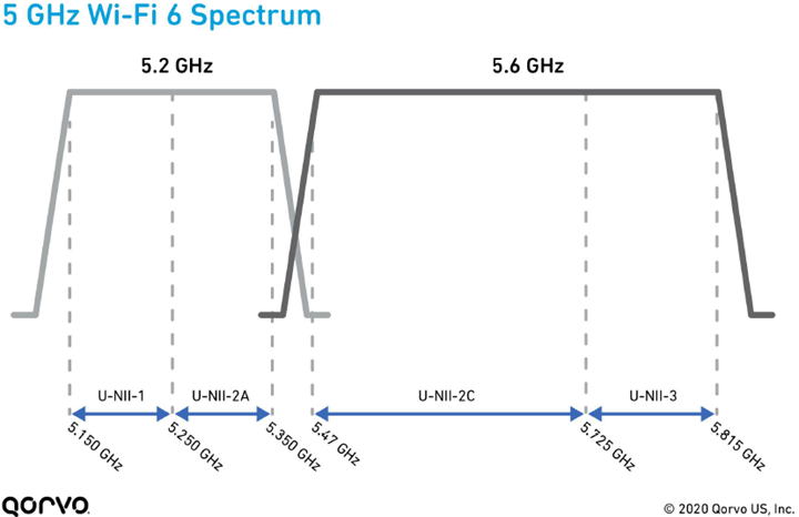
Tri-band Wi-Fi – The need for data capacity and coverage has led to an explosion of the tri-band architecture of 2.4 GHz, 5.2 GHz and 5.6 GHz bands in gateways and end-nodes, as shown in Figure 4 below. It allows users to connect more devices to the internet using the 5 GHz spectrum in a more efficient way. For example, if you’re using a home mesh system with multiple routers to cover a larger space, the second 5.6 GHz band acts as a dedicated communications line between the two routers to speed up the entire system by as much as 180% over dual-band configurations.

Figure 4: 5.2 GHz & 5.6 GHz Wi-Fi filter response bandwidths and bandedge parameters
Higher temperature conditions – New gateway designs require smaller form factors, sometimes half the size of previous product versions, with a higher number of RF antenna pathways (a tri-band router can have upwards of 8 RF pathways). Because of the confined space and increased number of antenna pathways, system thermal management becomes even more challenging. There are also gateway applications with higher temperatures at the extremes of -20⁰C to +95⁰C for outside environments.
Smaller form factor & integration – Today’s gateway devices are sleeker, stylish and have smaller form factors. The demand for smaller gateway form factors is pushing Wi-Fi integrated circuits to shrink as well. Additionally, this is moving semiconductor technologies toward creating smaller and thinner devices to mitigate system designer costs.
To accommodate this initiative, Qorvo has also integrated its filter technology into complete RF front-end designs to help system designers reduce design time, meet smaller size requirements, and increase time-to-market.

Figure 5: Comparison of 5 GHz ceramic versus Qorvo QPQ1903 BAW filters
As system designers continue to meet higher frequency demand initiatives – brought on by the hunger for more frequency spectrum – design challenges increase. New hurdles like system pathloss, signal attenuation, designs in higher frequency realms and meeting coexistence standards are becoming more prevalent. Qorvo has worked extensively with network standards bodies and customers across the globe to ensure their designs meet all compliance needs. We work hard to provide products that meet these highly sought-after specifications with additional margin. This proactive work ultimately allows our customers to concentrate on delivering best-in-class products rather than trying to mitigate difficult design and certification issues.
Have another topic that you would like Qorvo experts to cover? Email your suggestions to the Qorvo Blog team and it could be featured in an upcoming post. Please include your contact information in the body of the email.
